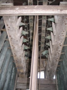
View of the chime action from below the treble end of the frame. Wooden rods from chimestand rise through center. Notes alternate between right (south) and left (north) sides. Hammer racks are beside the tubular bells; transfer racks are above. Five hammers at bass end (distant) are heavier design than the rest.
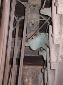
Closeup of bass end of south half of chime. Triangular transfer levers, pivoted at the top, convert the downward pull of action rods to an upward pull on the back of the hammers, throwing them against the tubular bells near their tops. Circular safety loops connect the ends of the triangular lever over the top of the rack. One connector is broken, allowing that hammer to rest on its safety peg; the corresponding action rod leans to the right.
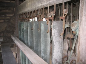
The north half of the frame, viewed from the outside. Each tube is suspended from a pair of J-hooks by a loop of wire rope, the ends of which are clamped around a bronze grommet. The original installation would have had manila rope suspension, with eye splices around the grommets. The wear spots on the tubes are evidence that the tubes were turned around when rehung, and that the rehang must have occurred several years after the original installation.
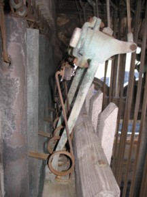
Closeup of chiming hammers (treble end). Each is cast bronze, pivoted at the bottom, with a wooden plug which strikes the tubular bell near its top. The plug is held in place with a clamping loop, so that it can be changed when necessary. A return spring straddles each hammer, to throw it back to its rest position after the strike.
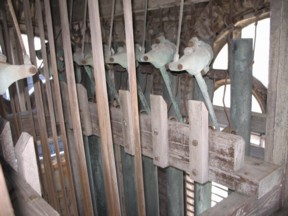
The south half of the frame, viewed from the inside. Hammers, return springs and safety pegs are visible through the row of action rods.
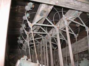
Transfer lever racks and associated action parts. One end of each triangular transfer lever is connected to the action rod from the chimestand; the other is connected to the pull rod for the hammer. Connected to both ends of the transfer lever is the safety loop, which passes over the top of the rack and carries counterweights. The gray spheres, each with a set-screw, are the original counterweights installed by Durfee. ; The greenish spheres, made in two parts which are bolted together around the safety loop, are later additions to balance the additional weight of the wooden rods that replace the original rope action.
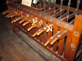
Chimestand front. Clearly this instrument is badly out of regulation; the drop of key #5 (which goes to the disconnected hammer seen above) is little worse than that of keys 12 and 14. The brass brackets on the end frame posts would have been for a removable stop bar, possibly intended for practice purposes since there is no locking facility visible.
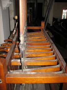
Chimestand side from above. The ladder for access to the belfry is just behind the far right corner post.
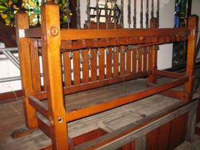
Chimestand rear. The near corner projects over part of the stairway up to the rear level of the balcony, and is supported there by extra framing. Some of the wooden bosses which originally camouflaged the frame connector bolts have since been lost.
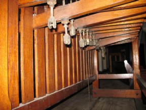
Chimestand side from below. The unused clevises on the underside of the keys would have been intended by McShane for use on connecting an auxiliary electric action, as seen in some complete chime installations by McShane.